Key Takeaways
- A complete welding symbol can include up to eight elements: reference line, arrow, basic weld symbol, dimensions, supplementary symbols, finish symbols, tail, and a specification or process reference.
- The four basic types of welds are groove (butt), fillet, slot, and plug.
- Where a weld symbol sits on the reference line tells you which side of the joint gets welded — below the line means the arrow side, above means the other side.
- AWS A2.4 is the standard governing welding symbols in North America; ISO 2553 is the international equivalent.
- Free, accurate welding symbol charts are available directly from AWS and several major welding equipment manufacturers — skip the unofficial versions floating around online.
What Are Welding Symbols?
Welding symbols are a standardized graphic shorthand used on engineering drawings to communicate exactly what type of weld is required, where it goes, how big it needs to be, and what additional steps are needed, without writing out a paragraph of instructions. They’re defined in North America by AWS A2.4, the Standard Symbols for Welding, Brazing, and Nondestructive Examination, with ISO 2553 serving as the equivalent international standard. Anyone who reads fabrication drawings — welders, drafters, inspectors, engineers — needs to be able to interpret these symbols correctly, since a misread symbol can mean the wrong weld type, wrong size, or weld on the wrong side of the joint. WeldFabWorld
Why It Matters Right Now
A welding symbol packs a surprising amount of information into a small graphic, and getting even one element wrong changes the whole instruction. A weld symbol placed below the reference line means the weld goes on the arrow side of the joint, while one placed above the line means the other side — and if it appears on both sides, the weld is required on both sides of the joint. Mixing that up on a structural drawing isn’t a small mistake; it can mean a weld in the wrong location on a part that’s already been fabricated. Pi Fabricators
The 8 Elements of a Welding Symbol
A complete welding symbol is made up of up to eight possible elements: reference line, arrow, basic weld symbol, dimensions, supplementary symbols, finish symbols, tail, and a specification, process, or other reference. Not every symbol uses all eight — many simple symbols only need three or four. Pi Fabricators
Reference Line
The horizontal line everything else attaches to. It’s the backbone of the symbol.
Arrow
Points to the joint location on the drawing and establishes which side is the “arrow side” for reading the rest of the symbol.
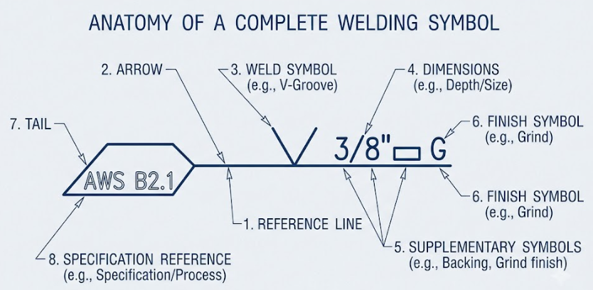
Basic Weld Symbol
The small graphic (triangle, V-shape, circle, etc.) indicating the type of weld required.
Dimensions
Size, length, and pitch information placed around the weld symbol.
Supplementary Symbols
Extras like the all-around symbol or field weld flag that add context beyond the basic weld type.
Finish Symbols
Indicate how the weld surface should be finished after welding — ground, machined, chipped, etc.
Tail
The forked end of the reference line, used to call out a welding process, specification, or procedure reference.
Specification/Process Reference
Often placed in the tail, this points to a welding procedure specification (WPS) or process code governing the weld.
Basic Weld Symbols You’ll See Most Often
Fillet Weld — a triangle symbol, used for the most common weld type in structural fabrication, joining two surfaces at roughly a right angle.
Groove Welds — several variations (square, V, bevel, U, J) used to join parts in the same plane, often requiring beveled edges.
Plug and Slot Welds — used in lap joints, filling a circular hole (plug) or elongated hole (slot) to join overlapping parts.
Spot and Seam Welds — common in resistance welding, indicating a series of point welds (spot) or a continuous welded seam.
The Four Basic Types of Welds
There are four basic types of welds: groove weld (also called a butt weld), fillet weld, slot weld, and plug weld. Each suits a different joint configuration and load requirement. slideshare
Groove (Butt) Weld — joins two members in the same plane, often the strongest option when full penetration is achieved, but typically requires more prep work like beveling.
Fillet Weld — the most commonly used weld in structural work, joining members at an angle, such as in T-joints and lap joints.
Slot Weld — an elongated hole filled with weld metal to join overlapping parts.
Plug Weld — similar to a slot weld but through a circular hole rather than an elongated one.
Where to Find a Reliable Welding Symbol Chart
The most reliable source is AWS itself — the American Welding Society publishes the official A2.4 standard and offers reference charts based on it. Several welding equipment manufacturers and fabrication shops also publish free, accurate symbol charts based directly on the AWS standard, often as downloadable PDFs intended for shop floor reference. When using a third-party chart, double-check it’s based on the current AWS A2.4 edition rather than an outdated or simplified version that might be missing supplementary symbols.
How to Read a Welding Symbol: Step-by-Step
- Find the arrow and reference line. Identify which member the arrow points to — this establishes the arrow side.
- Check symbol placement above or below the line. Below means arrow side, above means other side, both means both sides of the joint.
- Identify the basic weld symbol. Match the graphic shape to the weld type — triangle for fillet, V-shape for V-groove, and so on.
- Read the dimensions around the symbol. Size typically sits to the left, length and pitch to the right.
- Check the tail for process or spec callouts. Not every symbol has one, but when present, it often points to a specific WPS or process requirement.
Common Mistakes When Reading Welding Symbols
- Confusing “weld symbol” with “welding symbol” — the weld symbol is just the small graphic shape (the triangle, the V); the welding symbol is the complete instruction built from up to eight elements.
- Misreading arrow side vs. other side — this single mistake can put a weld on the wrong side of an entire joint.
- Ignoring the tail — skipping a process or specification callout in the tail can mean missing a required procedure or material spec.
- Assuming all symbols use all eight elements — most simple symbols only need three or four; expecting every element on every drawing leads to confusion.
- Relying on outdated or simplified charts — some free charts circulating online omit supplementary and finish symbols entirely, leaving gaps in interpretation.
Wrapping Up
Welding symbols pack a lot of information into a small graphic, but once you understand the eight possible elements and how arrow-side versus other-side placement works, reading a fabrication drawing stops being guesswork. Keep a reliable AWS-based chart on hand, and the rest comes down to recognizing the basic weld symbol shapes you’ll see again and again.
Frequently Asked Questions
What are the basic welding symbols?
The most common basic weld symbols include the fillet weld (a triangle), groove welds in several variations (square, V, bevel, U, J), plug and slot welds, and spot and seam welds used in resistance welding. Each symbol’s shape corresponds directly to the cross-section or configuration of that weld type.
What are the 8 elements of welding symbols?
A complete welding symbol can include a reference line, arrow, basic weld symbol, dimensions, supplementary symbols, finish symbols, tail, and a specification or process reference. Not every symbol uses all eight — simpler welds often only need a handful of these elements.
What are the 7 basic types of welding?
There’s no single universally agreed list, since sources group welding processes differently, but a commonly cited set includes stick welding (SMAW), MIG welding (GMAW), TIG welding (GTAW), flux-core welding (FCAW), submerged arc welding (SAW), oxy-fuel/gas welding, and resistance/spot welding. These cover the processes most commonly taught and used across general fabrication.
Where can I find a welding symbol chart?
The American Welding Society publishes the official AWS A2.4 standard chart, which is the most reliable source. Many welding equipment manufacturers and fabrication shops also offer free downloadable charts based on that standard — just confirm they reflect the current edition before relying on one.
What are the four basic welds?
The four basic types of welds are the groove (or butt) weld, the fillet weld, the slot weld, and the plug weld. Fillet and groove welds are by far the most commonly used in general fabrication, while slot and plug welds are reserved for specific lap joint applications.